


MARCH 2024, ISSUE 3
“A free-hand sketch, with all its imperfections, often opens a dialogue, invites users to participate in the process and suggests with welcoming arms that nothing’s set in stone.”
– David Drazil, Architect and Author
The selection of the architect may be the most consequential decision you will make once you decide to build your house. Don’t take it lightly. As with the site selection, do your due diligence. Some hire their architect based solely on fee. This is a mistake. A low fee equates to a reduced scope of work, which then leads to an inferior final product. A good architect will put a ton of blood, sweat, and tears into your project. This is reflected in the fee. For a serious architect to perform full services on a single family detached home, expect to pay 8 to 12 percent of the construction cost, maybe more if it’s an addition and alterations project or is very small or complex. (For a brief overview of the effort involved, reference Phases of Architectural Sevices.) So ask around. Look at websites and social media. Interview. The goal should be to find someone with whom you have a good rapport and whose work you admire.
In this post we’ll talk about the first of the five phases of service that architects typically provide – schematic design. Using the dinky House as a case study, let’s take a look at the process. I’ll be describing my particular process, which has evolved (and continues to evolve) based on my ideas of architecture, my working knowledge, and my skillset in conveying architectural form. There is no standard process that all architects follow. I’ve developed and refined my process over four decades of continuous practice. During the schematic design phase, I use the most basic of architectural tools – pen and paper. I address this in more detail in the architecture connection blog, architecture + SKETCHING: Drawing on Imagination, but basically I feel that freehand sketching is the most intuitive and direct way to get ideas out of my head and onto paper. After all, ideas stuck in the head of an architect never get seen by a client or built by a contractor. Eventually seeing designs conceived in my head later realized in built form is, for me, the most gratifying part of being an architect. Enough architalkure. Now, back to my schematic design process.

Before I even start drawing, I work with the client to flesh out the program. What are the rooms and spaces desired? How do they relate to each other? What is their function. Where should they be positioned relative to sun, views, neighbors? What if any limitation are posed in getting the car on site? Once I have the list of spaces, I draw them to scale as simple rectangles, something I’ve dubbed a spacial program. This gives me a good graphic representation of what I’m dealing with. I can also add up the square footage, add some for circulation, and get a rough estimate of the square footage requirements. Multiplying that by an estimated square foot cost gives me and my client a pretty good idea of the funds that will be required to meet the program requirements. With that, we know if we can play loose with the design and not worry if it grows a bit, or do we need to try and make it stealthy, using shared spaces and other tricks? The last thing either of us want to do is to invest a large amount of time and energy into a design we both love, and then have a builder bid it and tell us that it has blown the budget. This scenario can play out under any circumstances, but I try to lessen the odds by starting out being as realistic as I can be.
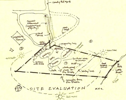
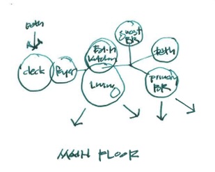
I next develop simple bubble diagrams to evaluate the site and house, showing spacial relationships without regard to scale, shape, or location. A space planning exercise follows, where all of the spaces are arranged in basic shapes, drawn to scale. The effect is almost a floor plan, but simpler , with no doors or windows. These diagrams illustrate spaces and their adjacencies to each other as well as to site features. It allows the client to focus on the relative size of the spaces and their relationships to each other without the distractions of a developed plan. With all of this accrued knowledge, I can now begin to develop what most clients recognize as architectural drawings – plans and elevations. I often start these as small scale drawings. I produce quick sketches on tracing paper, lay them over more quick sketches to advance them, and I do this over and over and over, until I finally get the design to a good stopping point that I can show the client. Figuring out exactly where to stop is hard because these sketches are never really completed to my satisfaction. It is normally the constraint of time that forces me to stop designing and put something presentable on paper.

The program I originally generated for a single story fishing cabin included a Foyer, Living Area, Eat-in Kitchen, Guest Bedroom, Primary Bedroom, and a large Bath, which doubles as the Laundry. As I’ve already mentioned, my wife and client, prompted the downstairs “Dormitory” which was comprised of a Sitting Area, Sleeping Area, and a Bath.
We can hear the soothing sounds of the shoals on the west side of the site, so we placed the entrance and deck where it can be experienced by anyone who enters the house. The house is linear and logically parallels the contours but is twisted to face a little east of south to capture views of the river. The north and especially the south sides of the house contain several large windows, strategically placed to frame views and allow for cross ventilation. The Foyer orients the visitor to the interior and leads to the “public” areas, comprised of the Eat-in Kitchen and the Living Area, projecting up and out to the southern vistas. The Primary Bedroom is opposite the Foyer, past the Stair and Bath, on the more private east end of the house and site. A small balcony off the Primary Bedroom allows views to the southeast, down to the river. The Primary Bedroom contains, as Frank Lloyd Wright would say, a place to nest and a place to perch (as further explained in the architectureconnection post Nesting & Perching.)
As opposed to what many think, the process of getting from the program to plans and elevations is very much an evolutionary one. I go through dozens, sometimes hundreds of sketches and overlays, developing and arranging rooms and spaces, and block out elevations and character sketches with numerous variations. It’s not easy to shape space! I try to work on both the plans and elevations together. After all, they are just different views of the same design. I never want to “finish the plan” and have to force elevations onto it. Ancillary to this process is the site plan, which also evolves along with the plans and elevations. My sketches tend to get increasingly more refined as the design evolves. Eventually I am able to complete the schematic design process. There is sometimes a fuzzy line between the phases of the architect’s work, but with solid preliminary floor plans, a couple of character sketches, and a well developed site plan, the schematic design phase is considered complete. The design will no doubt change as we move to the next phase, design development, but the DNA is pretty well set.
Once the architect and client agree that the floor plans convey the approiorate rooms, spaces and relationship, and that the elevations convey the desired general massing and style, and the site plan properly places the building and allow good vehicular access, it is time to move on to the next phase. That’s where we’ll pick up in the next issue – design development: How it Works.


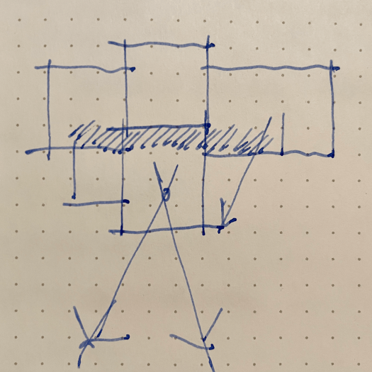
What about the parti’? Let me explain. Archisoup defines a parti’ diagram as “a simple sketch that communicates the overall concept for a design project.” I can’t speak for others, but I never sit down with the expressed purpose of drawing a parti’ diagram; however, I can usually go back through my sketches and find it after-the-fact. The first image at the top of this post is one of the first sketches I drew. This parti’ diagram is a simple but important sketch that I recently found, amazingly, in one of my sketchbooks. (See Bonus Material.) Had I not found it, this blog post title “Parti’ Time” would make little sense. My parti’ diagram captures the “big idea” – a collection of spaces along a circulation spine, arranged to allow distant vistas. All of the diagrams and sketches developed in the schematic design phase are just stems, leaves, and petals sprouting from that seed.
BONUS Material:
I have long admired architects and designers that are able to use sketchbooks like diaries – regularly logging entries. Once I was out of college, where we were often required to keep sketchbooks, I pretty much abandoned the practice. I really do like the idea of having all my sketches for a particular project in one place, where I can reference and track its evolution, Unfortunately it does not work for me as a practical matter. That’s why there are so many different looking sketches in this post.
Perhaps the main reason I don’t keep a sketchbook is that it is never around when I need it. (I know deep inside that the problem lies with me, not my sketchbook.) I normally work down to the last possible moment, so the last thing I have time to do is to start a sketchbook search. I can easily grab one of several notebooks or rolls of tracing paper that are alway laying around my drawing table and scattered throughout the studio.
I also have a weird obsession with pens and paper. They are not all the same. (Sorry, but I have to geek out for minute.) I normally prefer a medium nib Lami Safari fountain pen on 12 inch wide canary tracing paper. I like white tracing paper if I’m going to be “coloring” with my Design markers. I also love Pilot Precis V5 and V7 pens – black for drawing and red for, well, red-lining. I also like the trusty #2 pencil. It is still as versatile and expressive as ever.

I draw a good bit outside the office – at jobsites, at home, in coffee shops, in restaurants, and while driving (just kidding)! In these scenarios, I usually still have one of my Lamys or Precise pens, but I replace my tracing paper with pieces of drywall or 2x4s, product manufacturer’s notepads, ruled notebook paper, napkins, the back of receipts, or whatever else I might find. When not in the office I am forced to be far less picky.

2 Replies to “schematic design: PARTI’ TIME”